(There’s a more recent post with updates to this sensor.)
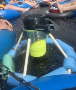
I rigged up a crude little water level sensor to monitor my Christmas tree and send me alerts when it gets thirsty. With the help of two strips of aluminum stuffed in a FoodSaver bag, an Adafruit HUZZAH32 – ESP32 Feather Board, and a little Arduino code, our humble tree has become part of the IoT revolution!
Physics lab flashback
The sensing probe that goes in the water is basically just a parallel plate capacitor straight out of undergrad physics. The water flows between the plates and works as a dielectric. The relative permittivity (aka dielectric constant) of water is about 80 times greater than air, which essentially means that there’s 80 times more capacitance when there’s water between the plates than when there’s air. As the water level rises, there’s water between a larger area of the plates, so the capacitance increases.
To see how well the theory held up in the real world, I started off by making a simple capacitor using two strips of aluminum separated by a sheet of paper.

The trusty Fluke measured 1.4 nF, which was surprisingly close to the theoretical value of 1.7 nF that I got from this online calculator.
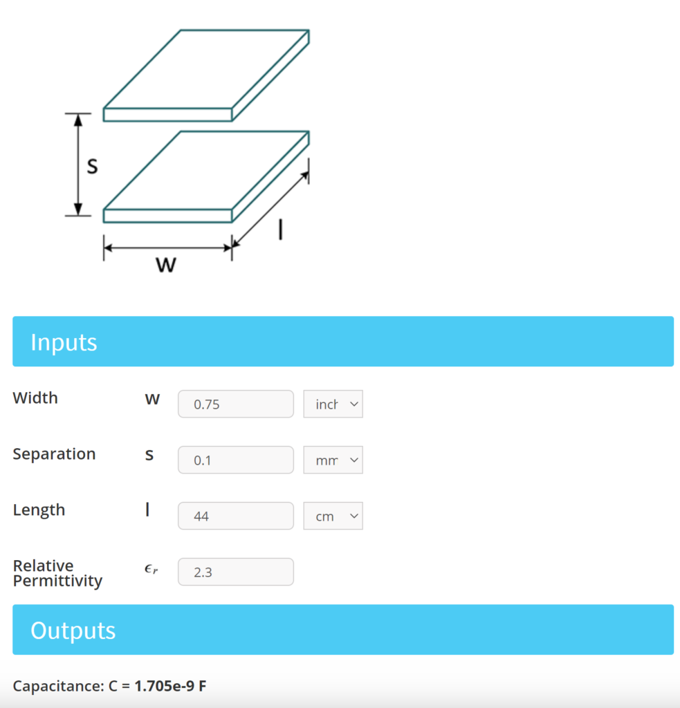
Based on the depth of the tree stand, I knew what the rough dimensions for the probe would need to be, but I didn’t really have a clue how much capacitance to expect from a parallel plate capacitor with those dimensions. It was encouraging to see it fall in the nanofarad range. I figured anything much less than that would be too small to reliably measure without some hardcore analog circuity.
With my sanity check complete, I started thinking of ways to hold the plates together while still allowing water to flow between them. Ideally, the gap should be uniform along the length of the plates for linearity and as close as possible to maximize the capacitance. I printed out a bunch of these little clips to do the job. They increased the gap quite a bit compared to the sheet of paper, but they held things together alright, so I kept my fingers crossed that they would still allow for a measurable amount of capacitance.


Feeling pretty good about how things were going, I filled up a pitcher of water and dropped the probe in. I was expecting something in the nanofarad range, but the measurement on the DMM was all over the map. After an hour or two of banging my head against the wall trying to hunt down noise sources and figure out where I went wrong, it finally dawned on me what was going on. Can you spot the problem?

Here’s a clue: another word for dielectric – the stuff between a capacitor’s plates – is insulator. It turns out water is a pretty decent conductor at DC and the lack of insulation on the plates meant there was a DC current flowing through the water that was making the DMM’s capacitance measurement go bananas. After a couple of sad attempts to insulate the plates, I stuffed everything in a box and put it on the shelf.
Round 2
Fast forward to this year and I decided to give it another go. I had been kicking around a couple different ideas for measuring the water level in the meantime. I considered some mechanical float-based solutions, but was ultimately drawn back to the capacitive probe. I researched a couple options for measuring the capacitance, including a chip built for this purpose, measuring the rise time of a pulse, using an array capacitive touch sensors, and a simple capacitor (AC) voltage divider circuit. The voltage divider seemed like the simplest option with what I had laying around, so that’s where I started.
But first I needed to tackle the insulation issue… In all of the “real” designs I’ve seen, the probe is made up of traces on a PCB and the insulation comes along for the ride in the form of the solder mask. I might make a custom PCB eventually, but at the time I didn’t have a design I was ready to commit to, or weeks to wait around for boards to get fabbed. I imagined I could get a similar effect by dipping the plates in some kind of enamel paint, but I didn’t feel like dealing with the mess or the dry time. So I tried different ways of covering the plates in plastic. Oddly enough, the FoodSaver ended up coming in clutch as a way to create a bag with two pockets that I could slide the plates into. Not sure why that isn’t featured in their informercials…
Once I had the circuit up and running, I played around with different orientations of the plates. It didn’t seem to make much difference whether the plates were parallel or co-planer. This was welcome news since the little clips I printed to hold the plates parallel didn’t fit with the extra layer of plastic anyway. I ditched the clips and went co-planer.
Transducing, done dirt cheap
Given the fact that there are pricey, dedicated chips for doing this kind of signal processing (albeit it with much greater accuracy and sensitivity), I wasn’t expecting much out of my dumb voltage divider approach. I figured it would probably be crippled by noise or interference, but was stoked to see how well it actually worked for this application!
Here’s the circuit:

A 3.3 V excitation pulse is applied across the probe (C_Probe) and a reference capacitor (C_Ref) by a GPIO pin on the microcontroller (ESP32). The ratio between the probe capacitance and the reference capacitance determines the voltage seen by the ADC. It works just like a basic DC resistor divider except the impedances are reactive instead of resistive.
Of course the impedance of each capacitor depends on frequency, but because the same frequency is applied to both the capacitors, the voltage division is independent of frequency. This is neat for two reasons. First, it allows the excitation to be a simple pulse, which is easy to create using the GPIO on the microcontroller. Second, the voltage at the ADC is essentially constant throughout the duration of the pulse, so taking one ADC sample is enough to make a measurement. From what I could tell, there’s no real support for capturing waveforms with the ADC in Arduino, so a single point measurement keeps things simple – no need to mess around with peak detection or fancy signal processing.
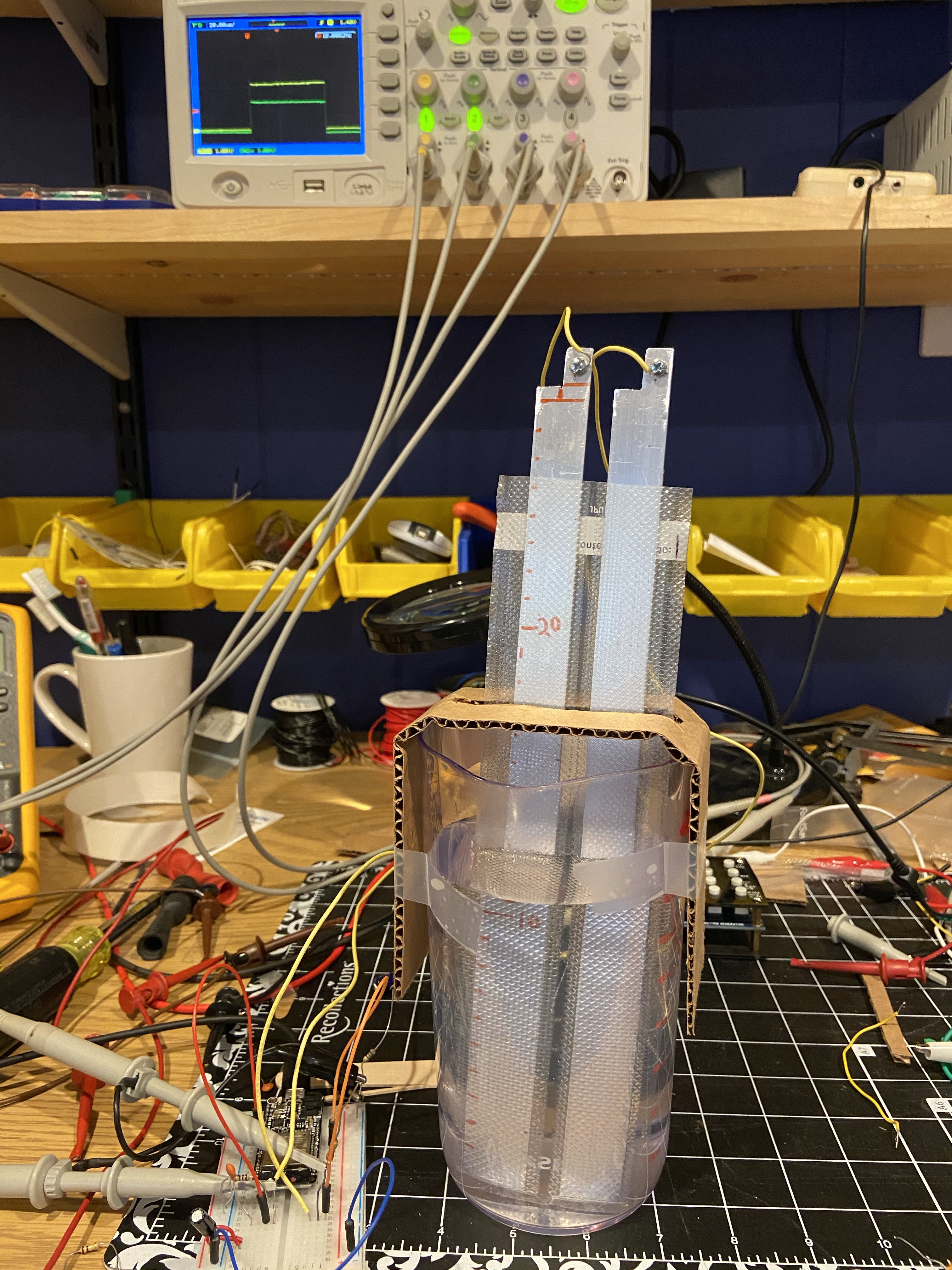
Here it is in action. The scope in the background shows the excitation (yellow) and the input to the ADC (green), which rises and falls with the water level.
Qualitatively the test looked promising, but I needed something more controlled to see how well it actually tracked the water depth. I had an RC airplane fuel pump laying around that I had picked up a couple years ago for a project, but never ended up using. (I was trying to make a Jägermeister shot chiller with a stack of Peltier thermoelectric coolers.) The pump was perfect for filling and emptying my test vessel without disturbing the setup.
Initial testing revealed a good amount of noise being picked up, causing the measurement to bounce around a bit. Slapping on a digital low-pass filter in the code was enough to stabilize things to my liking.
Here’s another test with the filtering in place showing the level on a 8-pixel NeoPixel stick.
Converting drips to bits
Determining the probe’s sensitivity ended up being a mostly empirical exercise. I manually recorded a bunch of filtered ADC values while cranking the water level up and down and let Excel do the rest. The plot shows the filtered ADC counts versus the true water depth for a couple filling cycles. The linear fit (green) is used in the code to convert the ADC value to a depth in millimeters.

At some point I tried to calculate the depth more accurately by accounting for the nonlinear relationship between the water depth and the voltage measured by the ADC. I don’t know if the ADC itself just isn’t very linear or there was a glitch in my algebra (much more likely), but I wasn’t seeing any improvement over just doing a linear fit, so I scrapped it.
The Code
I chose the HUZZAH32 because I wanted an easy way to push the data to the cloud, specifically Adafruit IO. I was planning on using CircuitPython, but apparently it doesn’t support Adafruit IO out of the box on the HUZZAH32. The Arduino platform had everything I needed, so I stuck with that.
In the current version, the program does the following:
- Setup peripherals and connect to Adafruit IO over Wi-Fi
- Repeatedly measure the water level and update the NeoPixel stick (not actually connected during normal operation to save power). This is done continuously for about 5 seconds to allow low-frequency noise to be filtered out.
- Publish the filtered water depth value along with the current battery voltage to Adafruit IO
- Put the ESP32 to sleep for 10 minutes
- Lather, rinse, repeat
This snippet shows the meat of the level-sensing code (the full listing is on GitHub):
void loop() {
  // read the sensor value with no excitation
  int noiseValue = analogRead(sensorPin);
  // turn on excitation
  digitalWrite(excitationPin, HIGH);
  // let things settle
  delayMicroseconds(50);
  // read the value from the sensor:
  int drivenValue = analogRead(sensorPin);
  // make it relative to the first point to reject low-frequency noise
  sensorValue = drivenValue - noiseValue;
  // reject low frequency noise further with a LPF
  filterOneLowpass.input(sensorValue);
  int filteredValue = filterOneLowpass.output();
  // turn off excitation
  digitalWrite(excitationPin, LOW);
  // calaculate something proportional to capacitance (doesn't work very well, so the depth is just mapped to the ADC linearly below)
  int cap = 1.0f / (4095.0/filteredValue - 1)*1000;
  // calculate depth as a linear function of the ADC (not super accurate, but close enough) using hardcoded offset and sensitivity found empirically
  int depthMm = (filteredValue - 210)/23;
  updateNeopixelLevel(depthMm);
  Serial.println(String(depthMm) + "    " + String(cap) + "  " + String(filteredValue) + "  " + String(sensorValue) + "  " + String(drivenValue) + "  " + String(noiseValue));
  updateFeed(depthMm, filteredValue);
}
Boxing it up
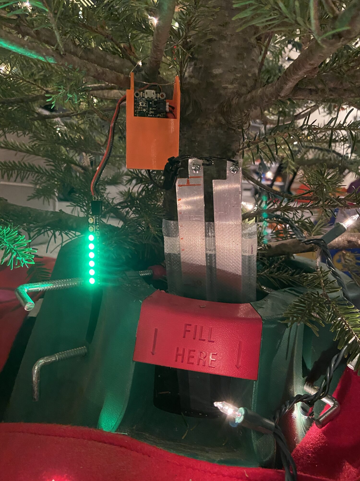
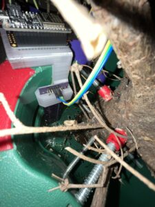
It seemed more than likely that something would go haywire after I installed it, so I wanted to keep the electronics and battery easily accessible. I came up with this goofy roofless birdhouse looking thing, stuffed the electronics inside, and hung it on the Christmas tree with some festive bus wire. The whole assembly is ugly as sin!
The groove along the outside to was intended to hold the NeoPixel strip. Even with the LEDs off, it draws too much current to be permanently wired to the board without adding a bunch of extra switching circuity, so I just left a dangling connector and only plug it in for debugging.


Power hungry
For having a built-in battery charging circuit, the HUZZAH32 isn’t very battery friendly. Even with the ESP32 in deep sleep, the USB serial converter chip still draws a whopping 7 mA! At that rate, my 400 mAH battery would be dead in just over two days without ever waking up the ESP32 to do anything. Luckily, I found a workaround to shut down the USB chip by adding a pull down resistor to one of the data lines. It sure would be nice to have some kind of switch or jumper on the board to disable that chip, but chopping up a USB cable and soldering on a resistor works in a pinch. The hack dropped the current below 1 mA, which should get me closer to two weeks on a single charge. That’s still not great for a low-power sensor, but it’s good enough to get me through the season with only a recharge or two.

The Cloud
The water level and battery voltage get published to Adafruit IO every 10 minutes. I setup a basic dashboard with some indicators and historical plots. It’s interesting to see how the tree’s thirstiness has diminished over time.
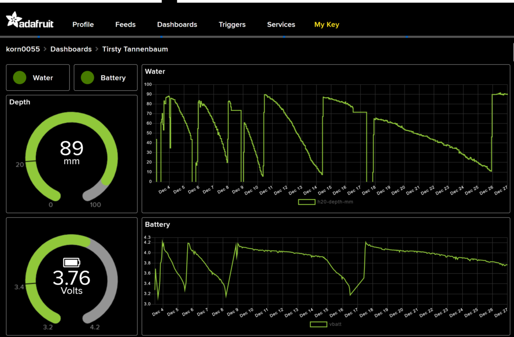
Unfortunately, you gotta pay to play if you want to send SMS or email notifications on Adafruit IO. But you can post to Slack for free using web hooks. I set up a trigger to let me know when the water level gets low.

Adafruit IO was a good choice for a n00b like me to shuffle some simple data up to the cloud. Its drag and drop dashboards made it easy to visualize the data with a couple charts and dials, but it’s pretty limited beyond that. In the future, I’ll probably check out a more feature rich IoT platform like ThingsBoard.
There’s plenty of fine tuning that could be done, but overall I would say this project was a success!

Your ADC is probably of the successive approximation type (SAR) which has a sample & hold circuitry, which charges up a small 5-20 pF capacitor with the voltage you provide. You also have some output impedance with the I/O pin, which you aren’t accounting for. That’s probably throwing your calculation off.
That’s a good point.
i’ve been using something similar for years on my sump pump tank. I just used insulated wires and string two sides in a pvc pipe then had that set as the capacitor for a schmitt trigger oscillator
That’s a cool idea! How accurate would you say it is? Do you have a rough idea of the capacitance per unit length (in water)? What range of frequencies does it output? Sorry for the 20 questions, just curious lol.
You can design the circuit for just about any frequency. A couple kilohertz would be the lowest frequency before the component values start to become impractical. If you can build the capacitor in the nanofarad range, you can generate playable audio tones with reasonable component values.
https://tinyurl.com/yapkwuvg
This circuit replicates one of the earliest synthesizers using two BJTs instead of a thyratron tube in a relaxation oscillator; the point is the same as with moser’s oscillator. It builds up voltage until it reaches the high threshold and then dumps the capacitor down to a lower threshold level. It’s not entirely temperature stable – but as the higher threshold level shifts, so does the lower threshold level because they’re both dependent on the base forward voltage. As long as both transistors are at the same temperature, it shouldn’t drift too much. Maybe 2% over 50F.
Note that the real deal will be off in frequency for smaller capacitor values, because falstad doesn’t model the Miller capacitances of the transistor. You can add those according to your part datasheet.
Interesting, I’ll have to play around with it. That’s a neat little simulation of it!
Here’s a fancier version of the same oscillator. This one uses a current mirror to copy the current from the left branch to the right branch and divide it smaller with the 200k resistor to charge with a constant current (given a constant input voltage).
https://tinyurl.com/y99vdu44
In both versions the frequency is proportional to 1/C but in the fancier setup the ramp is linear. With this, I’ve also added an rail-to-rail op-amp buffer to shift the signal to a square wave that would be easily read by a MCU. With a linear sawtooth waveform, it doesn’t matter which reference voltage you set, you always get a 50:50 square wave, so you can measure the width of an individual pulse to get the signal period: the inverse of frequency is directly proportional to C so you hardly have to do any math. Of course you would count many pulses, maybe a hundred or a thousand to get a good average. You also have a built-in analog comparator in some chips, such the ATMega328P (Arduino Uno etc.), so you could omit the op-amp and use that instead. The external op-amp just offers a very high input impedance so you’re not disturbing the circuit so much.
However, with more transistor bases in series it is now less temperature stable. The circuit could be characterized with LTSpice and compensated by adding a suitable NTC/PTC resistor with the 200k to adjust the current by a similar amount, but if you’re always measuring near room temperature it hardly matters. (or compensate in software)
Correction: the pulse width does vary from 50:50 depending on your reference voltage. For any fixed value, your pulse width will still be proportional to C, so you could use this feature to calibrate the circuit with a trimmer. Then you can have two different sensors with slightly different frequencies still reporting the same pulse period for the same water level.
Yeah I don’t think this thing would be straying too far from room temp, so the temperature stability stuff should be ok. I’ll have to give this a shot when I get a chance. In general, it seems like this capacitance to frequency approach has the potential to be more accurate than the voltage divider since I don’t have to sample analog signals with the ADC.